Digital Inputs – How to Wire Digital Inputs of Ace PLC
All Ace PLCs accept some number of digital inputs. Digital inputs sense binary status, such as on/off, switch open/closed, etc.
The Ace PLC can interface any DC voltage signal between 3 and 30VDC. Typical system designs utilize 5V, 12V or 24VDC power supplies, which are all within the Ace’s signal range.
Any connection to DC voltage between 3 and 30VDC is sensed as a ‘1’. Any connection to ground (or voltage below 0.8VDC) or an open connection is sensed as ‘0’. The ground reference of the signal must be connected to the ground terminal pin next to signal 1, or to the PLC’s input power ground.
The figure on the right shows a variety of typical digital input signals that may be connected to Ace digital inputs. Some of the more common ones include :
Switches, buttons, limit switches, etc.. : Connect one side to positive DC power (from a supply whose ground is connected to the PLC ground) Connect the other side of the switch to the digital input
Logic level signals |
 |
The last pin on each digital input port connector provides a voltage (connected to the 5V power input, through a 10 ohm resistor and a diode) which is used by the Optocouple Input Terminal modules. It can also be used to supply “wetting voltage” to dry contact inputs.
Plugs wiring

Wiring the NPN Input of my Ace PLC to Dry Contact (Push Button, Contact,..)
With External Voltage
Nothing on the (+) of the Ace PLC.
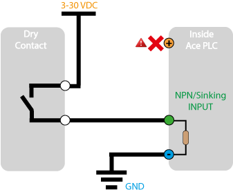
With Voltage Provide by the Ace PLC
5 VDC is only for dry contact and for “wet” lead wire. Do not use it to power anything.

Wiring the NPN Input of my Ace PLC to Encoder or PNP Device
Device With Internal Pull-up Resistor
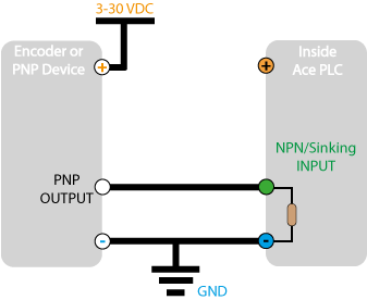
Device Without Internal Pull-up Resistor
Some entry-level devices do not include a pull-up resistor.

Internally, as part of the protection circuit, each digital input is pulled to ground through a 10K ohm resistor. This pull down resistor ensures that the digital input shows up as inactive when nothing is connected or the connection just sources voltage when it is active.
Ace digital inputs and the Ace CPU are very fast. For a small program, the logic scan and input scan can occur 5 times per millisecond. At this rate, mechanical contact bounce can signal the program that an input is changing rapidly – which can be a problem.
| To alleviate this situation, vBuilder has an option to allow you to set a debounce time on digital inputs. A debounced digital input will not report a change of state until that change has been continuous for the set debounce time. |  |
| Note that debounce does not apply to inputs configured as high speed pulse counter inputs. | |
Using vBuilder, 3 high speed pulse counters can be configured for basic high speed pulse counting (one digital input), or quadrature pulse counting (two digital inputs). The same signal level requirements apply, as listed above. For digital inputs that are AC signals, the Ace’s digital input ports can be connected to Velocio Optocoupled Input Terminal Block modules. These modules interface 24VAC or 120VAC signals. A cable, supplied with each terminal block module is then connected to the Ace digital input port. The Optocoupler Input Terminal Block modules convert the AC signals to the proper DC levels to the PLC.
Find this information in the Ace User Guide