How to Wire the Digital Outputs of the Ace PLC ?
About outputs of the Ace PLCs
Ace digital outputs are Sinking/NPN transistor outputs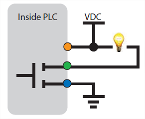
Which means that they provide the ground connection turn on a load. When switched on under program control, they complete the circuit to turn on any connected DC device up to 30VDC and 300mA.
All loads connected to a digital output port should be connected to the same DC supply. The load power supply ground must be connected to the ground (next to signal 1) of the output port.
About NPN (Sinking) and PNP (Sourcing) for Inputs/Outputs
Inputs NPN and PNP :
|
NPN (Sinking) Inputs = Ace PLCs Inputs = Positive logic
|
 |
|
PNP (Sourcing) Inputs = Negative logic
|
 |
Outputs NPN and PNP :
|
NPN (Sinking) Outputs = Ace PLCs Outputs = Negative logic
|
 |
|
PNP (Sourcing) Outputs = Positive logic
|
 |
How does outputs work ?Each output is connected, through a 33K ohm resistor to the VO terminal pin (next to output 6). This acts as a weak pull up. When the output is off (logic state 0), the output will be pulled up to the voltage at the VO terminal. If no power supply connection is made to the VO terminal, the voltage at the VO terminal will come through a 10 ohm resistor and an isolation diode, resulting in a voltage approximately 0.7V below the 5V supply to the PLC. This is enough to allow the PLC outputs to directly interface TTL circuits. If voltage is connected from an external source to the VO terminal, inactive outputs will pull up to the external source voltage. If AC power, or higher power DC needs to be switched, the Ace’s digital output ports can be connected to a Relay Terminal Block module, through a short standard cable, supplied with the module. With a Relay module, up to 250VAC and 5 Amps can be switched under program control. The cable diagram connection to the PLC digital output port pluggable connector is illustrated in the Relay Terminal Block module documentation. |
 |
Plugs wiring

Wiring the NPN Output of my Ace PLC to Relay

Wiring the NPN Output of my Ace PLC to Indicator Light

Wiring the NPN Output of my Ace PLC to a PNP Input Device
You can add our Optocoupled Sourcing Transistor Board TBTN06-35H (see our Shop page)
Or… Add a pullup resistor of 2.2 kΩ… But in this case the logic will be inversed.

For reverse the logic of output in your program, add this program (example for outputs D and E outputs) at the beginning of your main program:
Here, we reverse the logic of 12 outputs (D1..D6 and E1..E6) by additing 255 with the Xor function of the Calculator tool.
You can named each “ROutBitXn” by any name you want.
