RC Servo Control – How to control the angle of a RC servo using a PWM output
RC Servo Motors are typically small motors limited in movement to 180 degrees. They have 3 wires: ground, power and control.
To control the position, you send a Pulse Width Modulated (PWM) signal to the control line. The percentage of On Time determines the angle the servo will move to.

Period: for most RC Servos is 20,000 microseconds (50Hz).
On Time: Velocio PLCs have sinking transistor type outputs. That means that when they are “ON” a ground connection is made. The documentation for most RC Servo motors will talk about ON time in terms of high voltage time. Thus you’ll invert the time mentioned in most documentation. Because of this, ON time will typically be values between 19,000 and 18,000 microseconds, where 18,500 microseconds represents center position.
Wiring PLC to RC Servo
You can directly control your RC servos using your Velocio PLC’s outputs.
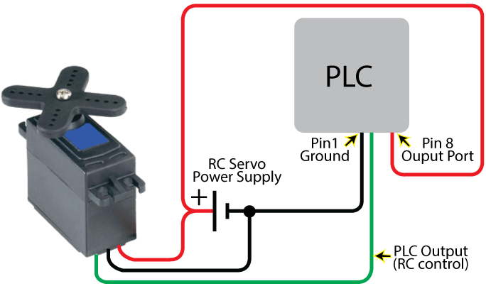
RC Servo Example All Wired Up
ACE PLCs allow you to control as many RC Servos as you have digital outputs. So, if your PLC has 18 digital outputs, you can control up to 18 servos. They will all use the same Period, but may use their own ON Time.
RC Servo Programming Example

Here are the files: RC-Servo.zip (Click to download. Then unzip and open using vBuilder.)
In State=1 we set the period to 20000 microseconds.
In State=2 we take an analog input and scale it so that the analog min corresponds to the RC’s min and the analog max corresponds to the RC’s max value. We then Start the PWM, telling it to use this newly scaled value as the ON Time.